![]()
![]()
![]()
![]()
![]()


|
|
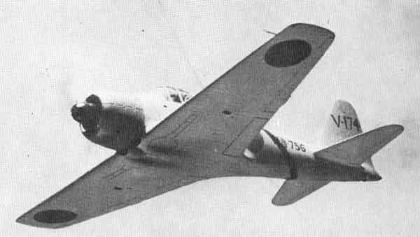
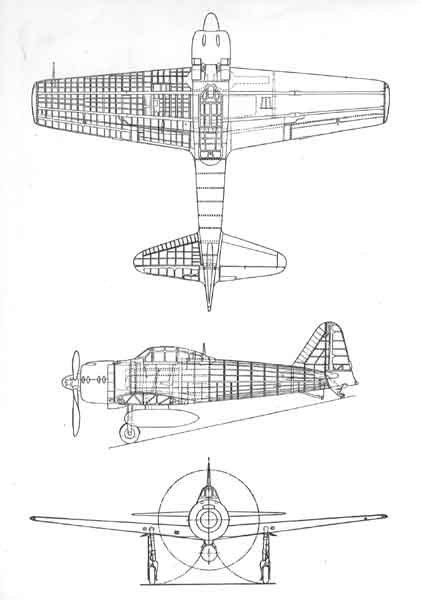
Design Analysis of the Zeke 32 (Hamp)(That's a Mitsubishi A6M3 Zero for those not up on WWII Allied code names. - Ed.)Text by John Foster, Jr., Managing Editor, "Aviation" Design Analysis No. 12
Section Index
Fore Fuselage
Light structural weight has been the prime consideration in designing the Hamp — now officially designated the Zeke 32— which was developed from the Jap’s workhorse Zero fighter.
Nothing has been spared to keep weight down, neither excessive manhours to manufacture complex units, nor increasing maintenance difficulties for ground crews. Lightening holes, for example, are used prolifically— even in the pilot’s seat—and diameters as small as half an inch are found throughout the craft. Outstanding of the weight saving measures is complete elimination of protective armor and self-sealing fuel tanks. It all results in a plane that is extremely vulnerable despite good maneuverability at medium speeds. This weight-saving design would indicate that the craft is flimsily built but such is not the case, for its strength compares favorably with many American-built planes.
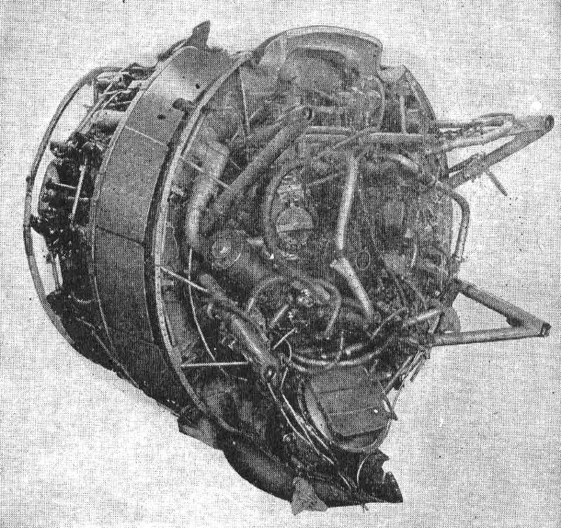
Principal difference between Zeke 32 and its predecessor is installation of a Nakajima—or Ishikawajima-built Sakae 21 engine — developed from Zeke’s Sakae 12—and substituting fixed squared wing tips for the earlier folding elliptical type. The Sakae 21 is a 14-cylinder, two row radial aircooled engine developing 1,020 hp. at 2,600 rpm. at 6,400 ft., turning a 10 ft. 3-in, diameter constant speed propeller which is very, very similar to Hamilton Standard design. As installed in Zeke 32 the engine has a down-draft carburetor and a two-speed blower in place of the older single speed. The installation has necessitated moving the. firewall aft eight in. and changing the cowling to put the air intake at the top. The re-designed cowling is an improvement, for it is cleaner and fits more snugly, having an OD of only 45 in. Built in upper and lower halves, it is carried on channel section rings supported by steel links on front and rear rocker boxes. The two halves are joined by hook type clamps and hand holes for access to the clamps are covered by fairing plates held in place by quick fasteners. Engine accessories are generally of sound design, but are not so sturdy as comparable American units whose design they follow. They are cooled by a scoop inside the cowling which brings air over the top of the cylinders, with several small ducts forcing air directly on some of the units. The engine as bolted to the 1 3/8-in. diameter mount ring by 13 lugs welded to the ring. Of conventional tubular construction, the engine mount has side tubes of 1 3/4-in, diameter; top and bottom tubes of 1 3/16-in, diameter, and attaches to the fuselage longerons by four high tensile bolts 5/8 in. in diameter and 1 5/8 in. long.
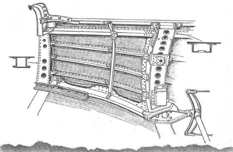
Fore FuselageHamp’s fuselage is built in two sections, the semi-monocoque fore section extending from the firewall 103 in. aft to former J, which is just aft of the wing trailing edge and just forward of the aft end of the cockpit canopy fairing. This section is built integrally with the wing and, in fact, is not structurally complete until riveted to the top wing skin, which forms the cockpit floor. Principal fore and aft members are four longerons, extending aft from the engine mount to former H, just forward of the wing trailing edge. The two top longerons are fairly heavy aluminum alloy hat-section members; the lower two are channel sections riveted to the upper wing skin and bolted to the spars. These longerons are flattened to accommodate formers B through H. Three 1/2-in. hat-shaped stringers are spaced evenly between the longerons and extend to former J.
Former A, to which is screwed the light sheet steel firewall, is a ring bulkhead containing the four engine mount bolts, while formers C and D shape skin around the fuselage fuel tank. Former D extends up from the front spar to the base of the windshield. Tapering to a width of 1 1/2 in. at the top, it is made up of two channels with a box facing and has varying-sized flanged lightening holes. A heavy tubular tie-through member at the top supports the two 7.7-mm. machine gun breeches and the top of the main instrument panel. A similar, but smaller diameter tubular tie-through member attaches to the bottom of the instrument panel and the middle of the three stringers.
Formers E and F are lightweight hat-shaped contour frames riveted to the longerons and stringers. Former G, a built-up hat-shaped structure, with lightening holes along the inner face extends up from the rear spar to the top longerons. Former H, some 6 1/2 in. aft, is a full contour built-up member extending from the lower longerons up through the fuselage top to form the turnover truss. Here again, lightening holes are much in evidence. Both fore and aft sides have some as large as four in. near the center, with another row of 1-in. diameter near the flange face which, in turn, has 1 in. holes spaced 1/2 in. apart. This member supports the pilot's seat via a torque tube to which two arms are riveted. The cutout in former H forms the only access to the accessory compartment, with entrance being gained by loosening two pins from the back support of the pilot's seat, and tilting it forward.
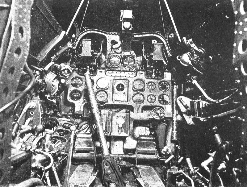
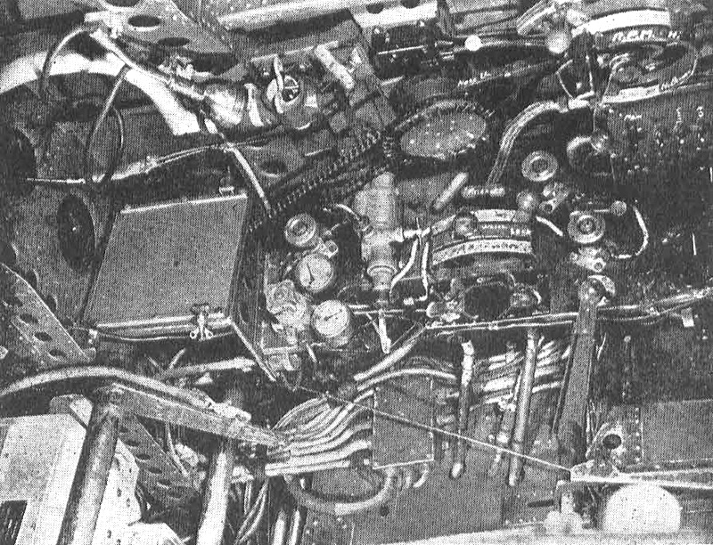
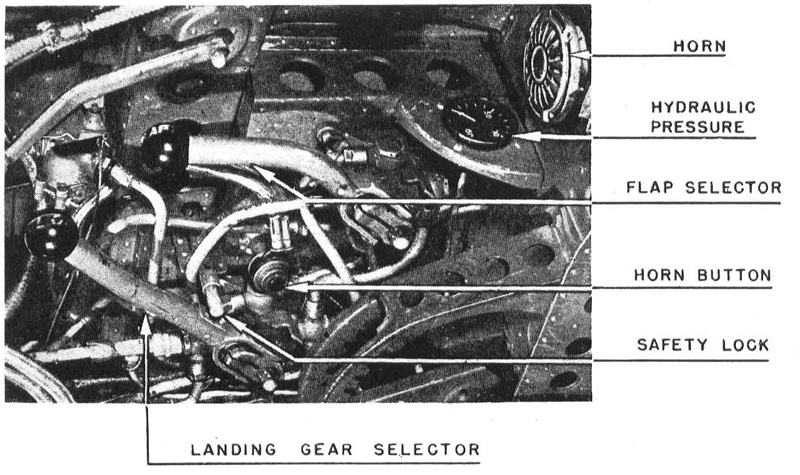
Former I is a light hat section frame. Former J is made up of 1 x 3/4 x 1/8-in. extruded angle section with 80 holes for 3/16-in. bolts spaced 1 1/2 in. apart forming a butt joint for joining to the aft fuselage section. Fixed windshield consists of three flat plates of glass, none of which is bullet-proof. The cockpit canopy likewise uses ordinary glass, all flat plate except for the segments in the curved top, edges of which are beveled and rubber-mounted. The light aluminum-and-plywood frame slides 27 in. on six roller in an extruded track section, and can be locked in four positions by a spring loaded pin sliding down into holes in the top of the track. Locking is accomplish either in or out of the cockpit by a handle set near the top of the forward part of the left side. No emergency jettisoning arrangement is provided. CockpitIn general the cockpit arrangement follows conventional practice except for size. While it's big enough for Japs, a typical American pilot in full flying gear would be pretty well jammed in. The top instrument panel includes the gunsight at the top, with the breeches of the two 7.7-mm. machine guns just below on either side, and the artificial horizon and bank and turn indicator centered. Also on this panel, mounted on Lord-type vibration absorbers, are the usual flight and engine instruments and switches. A panel on the pilot's left contains the throttle and gun quadrant; fuel tank selectors; hydraulic system controls; electric switchbox, etc. An unusual item on this panel, is a parachute static line hook. The panel on the right side contains mechanical cowl flap controls; radio controls; landing gear controls; arrestor hook release; fresh air tube; etc. Apparently cockpit heating equipment is not standard, but some planes have electric heaters around the air intake. Also on this side is the lever for raising or lowering the pilot's seat which is adjustable only up and down. The lever has a push button like an automobile emergency brake, but no ratchet -- merely a square tooth quadrant. A shock cord bungee passing over two pulleys on the turnover truss pull the supporting arms upward.
Entrance to the cockpit is from the left side, via three retracting steps and
two hand grips, all of which are spring loaded and released by very
smooth-fitting flush push buttons. One button releases the lower step-which
drops down out of the fuselage just aft of the trailing edge and one which comes
out the fuselage side just above the wing. Individual buttons are used for the
other steps and grips. The steps Although these steps and grips must add considerably to the man-hours involved in production, they perhaps save weight which would be necessary if heavier skin were put on the wing. Too, they help maintain clean aerodynamic design and do not necessitate breaking up the finish, which is exceptionally smooth all over the plane. Throughout the cockpit, wherever possible, brackets or supports are located between spanwise and lengthwise members so as to give a little additional strength.
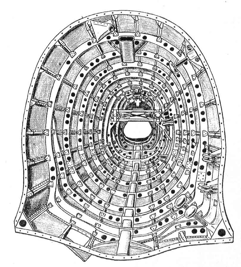
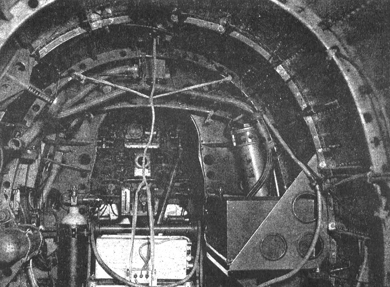
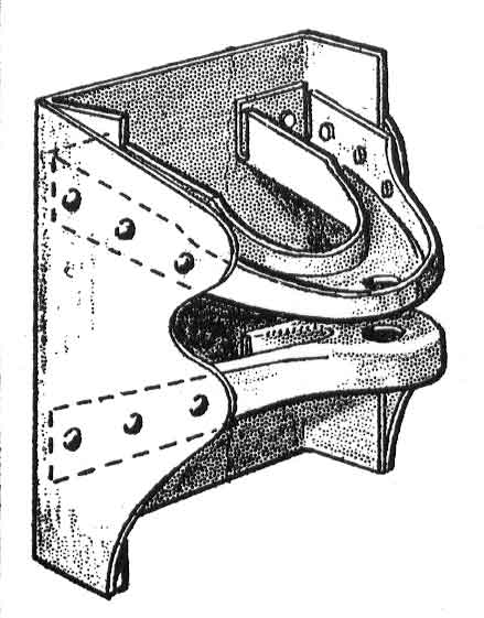
AccessoriesA compressed air cylinder; battery; DF radio receiver; hydraulic fluid reservoir; and oxygen cylinders are located aft of the pilot's seat between formers H and J. The oxygen cylinders can be re-charged from the outside by removing a flush-fitting plate held in place by a quick fastener to expose the connection and gage. In this section, too, brackets are arranged where possible to give some added strength. Aft FuselageAft section of the fuselage is full monocoque, extending from former K, which is butt-bolted to former J, but of lighter material, to former V, a distance of 144 in. All except L and N are full circumference, spaced 16 in. apart, and are J section, and those near the front end are 1 1/2 in. deep. These are built up in three sections, lap-jointed and riveted. Gages vary from .048 for the front lower sections, through .035 at the top. to .018 for those near the aft end. All the formers have standard cutouts for the stringers, with 3/4-in. lightening holes between stringers. There are 22 Z-shaped 1/2-in. deep stringers in the aft fuselage section, spaced approximately 6 in. apart at the fore end. All have four right angle clips for attaching to the frames. A built-up hat-section longeron extends along the bottom from former K to aft of former S, where the arrestor gear hook attachment is made. Formers S and U carry tubes for stabilizer spar attachments and elevator trim tab control equipment. Former V is built up of a channel section frame supporting the fin post, bottom rudder hinge and the tail wheel drag yoke fitting which is riveted to the bottom. This member is not parallel to the other formers, since the bottom is farther aft, putting it nearly vertical to the ground line, when the craft is in three point position. Three stamped brackets on each side serve to anchor quick fasteners on the tail cone.
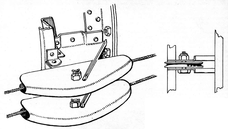
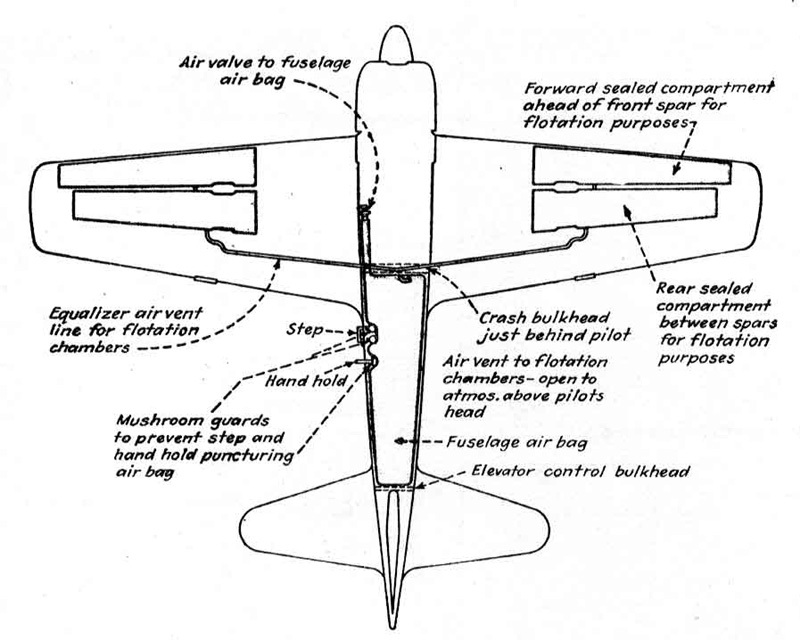
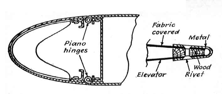
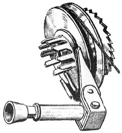
Tail ConeThis tail cone is comprised of two stamped alloy sheets with two J and two L-section stiffeners riveted inside each half. Small fairings extending out to the elevator also serve as stiffeners. It has a depth of 20 in. where it attaches to the fuselage; is 31 1/4 in. long at the top and 36 in. long at the bottom, where a formation light fits into the aft end. Three quick fasteners and ten screws on each side hold it in place, and a canvas dust catcher is screwed on and attached to the tail wheel drag yoke by a piano hinge. A bayonet plug connection is provided for the formation light. Removal of the tail cone exposes the tail wheel and combination retracting unit-oleo shock, and is one of the very few features of Hamp which would get any enthusiasm from a maintenance man. Skin. on both fore and aft fuselage sections is of lighter alloy than is customarily used on occidental planes, that on the fore fuselage being .048 gage on the lower portion and .035 near the top, and .018 for all the aft section. It is flush riveted throughout, with all fore-and-aft joints being lapped, others butted. Also throughout Hamp, small rivets are used, few being larger than 1/8-in., some being only 1/32-in. Despite the rivet sizes, there is no evidence on the craft studied to indicate a lack of strength, nor were there any indications of sloppy workmanship. Flotation GearHamp's main flotation gear for overwater operations consists simply of a large water-proof canvas bag in the aft fuselage section. This is connected to a tube leading to a barrel-type valve on the left side of the cockpit. Thus, when faced with a forced water landing, the pilot opens the valve, allowing the bag to be inflated by pressure of the air rushing in through the intake, with the valve being closed when the bag is fully inflated. The main bag is not connected with the wing flotation gear, to be covered in the discussion of the wing. The arrester gear, which appears to be left on the craft whether or not it is operating from a carrier, is built up of a T-extrusion with the forged hook riveted on. Extension and retraction is by means of a flexible cable running from a crank set in the right side of the cockpit. This handle incorporates its own lock, for the handle can be pivoted in toward the axle and locked into teeth extending out from the hub.
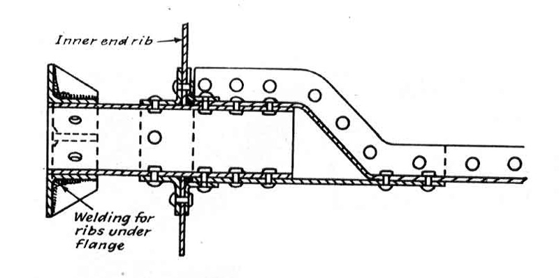
StabilizerStabilizer is two-spar full cantilever type, attaching to the tubes running through fuselage formers S and U by two shear taper pins on each spar. These tubes extend out 1 7/8 in. from the monocoque to the bolt centers, the gap being covered by a fillet extending back to the tail cone. Inboard stabilizer ribs are built-up truss type; the other seven are conventional stamped flanged aluminum alloy with lightening holes. Two spanwise channel stringers are used, one extending out to the tip, the other ending at the fifth rib. The leading edge has intercostals between each of the ribs. This section is attached to the front spar by top and bottom piano hinges. The skin is all flush-riveted, the gage for the leading edge being .025; the remainder .018. Skin extends aft of the rear spar ,and both top and bottom surfaces are crimped to form hoods over the elevators.
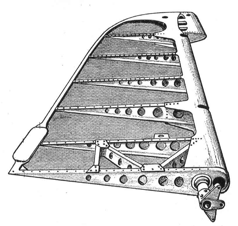
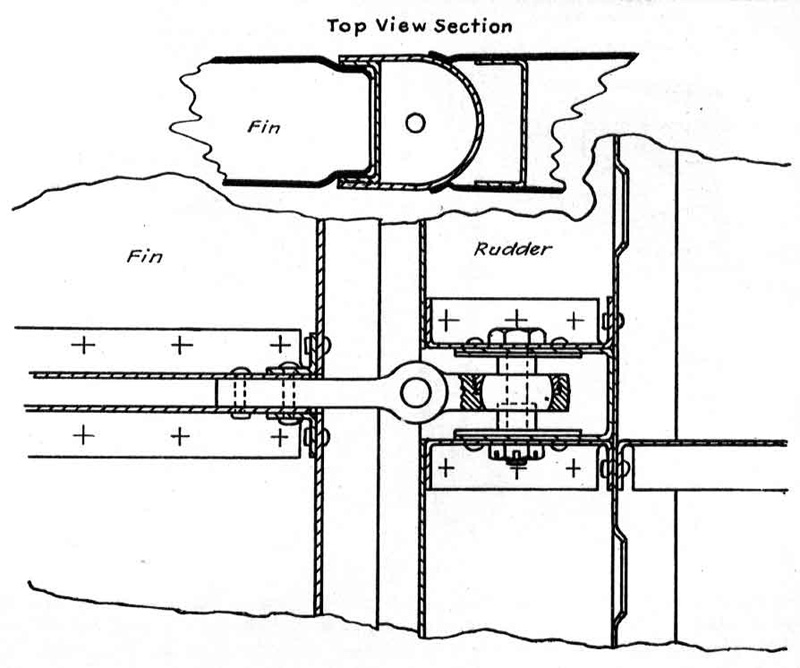
ElevatorsFabric-covered elevators follow conventional construction, with single spar and stamped flanged ribs having lightening holes 3/4-in. apart. Fabric is sewed on in the old style, rather than being attached by metal clips or wire. The spar root forms a box into which the torque tube is riveted, this tube in turn being butt-bolted to a torque tube mounted in the aft fuselage with the mass balance attached to it. One craft examined had stop-cables attached to the- horn, possibly to prevent green pilots from over controlling. Elevators have three self-aligning ball bearing attachments for connection with the Stabilizer. Elevators are the only control surfaces having trim tabs adjustable in the air. Operation of the tabs is by a vernier drum in the cockpit from which cables lead to a gear box mounted on former R. A short length of chain gives positive drive to the gears and a crossed cable drive carries motion to the right hand tab. Universal joints are installed just behind the gear boxes, with torque tubes from there to another pair of universal joints just ahead of the elevator torque tubes. A small crank turning in a slot in the tubular tab spar serves to change its angle. It is quite possible that more than one Jap pilot has had trouble with his tabs, for no provision has been made to prevent fouling of the crossed cable turnbuckles, short little gadgets which apparently are necessary to keep the cables tight enough to give the necessary drive. Fin and RudderThe vertical fin is built integrally with the fuselage except for the 10-in. deep leading edge, which can be detached by removal of wires from piano hinges on either side. Backed by intercostals and ribs 5 1/4-in. apart, skin on the leading edge is .025 gage; that along the sides is .016 and, as is the case with the stabilizer, skin is carried aft of the rear spar and crimped on either side to form a horn over the rudder. Of two-spar construction the fin has four stamped, flanged horizontal ribs. Conventional design is followed in the fabric covered rudder, except that the small metal trim tab is adjustable only on the ground. The single spar is stamped, flanged and with lightening holes as are the ribs. Aerodynamic balance horn, of some 46 sq. in., is set at the top, fitting into a cutout in the fin. Three hinge points have self aligning ball bearings and the torque tube mounted on the bottom end is within the fuselage. The rudder horn has a 5-in. spread, and some Hamps have had wooden stop blocks installed in the hinge fitting at the horn. This installation, like the cables on the elevators, may possibly be to prevent green pilots from over controlling.
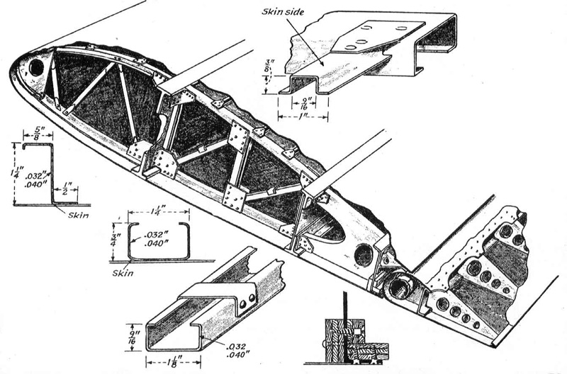
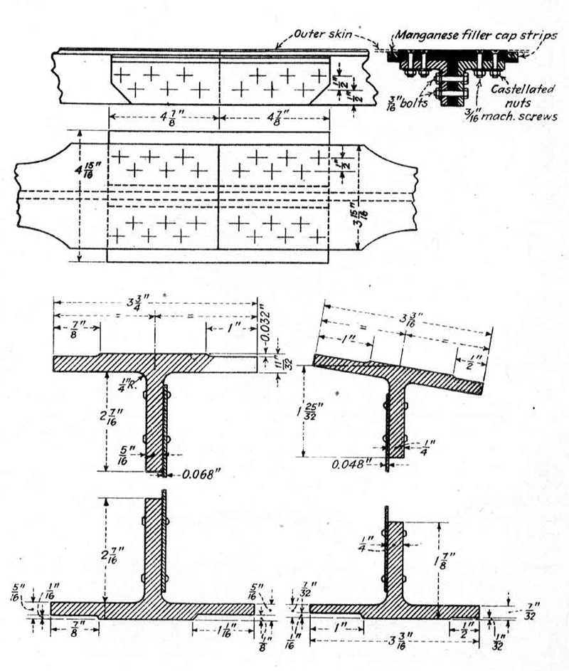
WingHamp's full cantilever wing presents several unorthodox features, outstanding of which is the splice on each side between ribs 10 and 11. (There are 24 ribs from fuselage side to the tip.) Since no design or production advantages are gained, use of the splices may be necessary either to limited length of extrusions available, or to limited milling bed lengths. With these splices, both front and rear spars are continuous from tip to tip, like those on the Focke-Wulf 190 (analyzed in AVIATION for October, 1944) so that if either side is damaged, the entire wing-together with integral fore fuselage section-must be replaced.
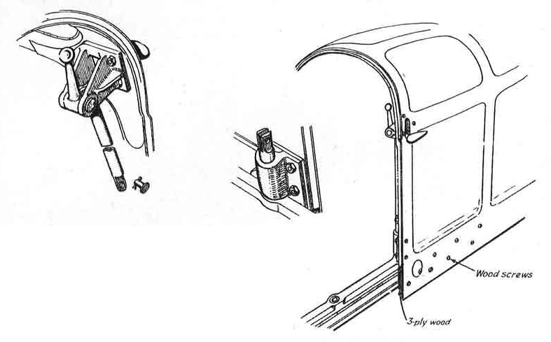
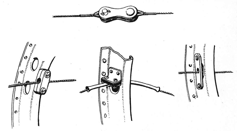
Spars are constant tapering I-beams, built up of extruded T-sections and solid 16-gage web reinforced every 8 in. by seven hat section and 17 L-section stiffeners on each side. The extrusions are milled on the outer surfaces to the depth of wing skin, so that the spars themselves form part of the upper and lower wing surfaces. Front spar is located at 32 percent of root chord and 27 percent of tip chord throughout the span, and the rear spar is at 65 percent of root chord and 64 of tip chord. Distance of spar centers on centerline of fuselage is 2 ft. 10 1/4 in., at tips it is 1 ft. 5 3/4 in. Neither upper nor lower surfaces between spars and ahead of the front spar appear to enter beam bending strength, since all hat-section spanwise stiffeners spaced 6 1/2 in. apart in these locations are intercostals, tieing only to ribs through flat skin reinforcements. Open truss type ribs, spaced 8 in. apart, are used in the leading edge except ribs 4 to 7 for landing gear attachment, and 7 and 8 between which are located the 20-mm. Oerliken cannon. Upper and lower chord sections are J-section joined at the leading edge by formed plates. Webs are 5/8-in. OD tubing, flattened at the ends 'to attach to the J-sections. Holes are drilled in the upper ends of the tubes to prevent cracking by flattening. Nose ribs at the landing gear attaching point and on either side of the cannon are built-up box truss type -- very complex units made of many small parts. 'Tween spar open truss type ribs are also spaced every 8-in. Every third rib is a compression member with formed C-section webs using double flanged gussets at all joints. Remaining ribs, although of similar truss type, are much lighter and are without gussets. Many of the C-sections in these ribs have clips at the mid-column point to tie the outstanding legs together and prevent collapse. Additional flotation gear is built into Hamp's wing through two airtight compartments formed by sealing off two boxes, one formed by the front and rear spar and ribs 8 and 22, the other formed by the front spar, leading edge and ribs 8 and 23. Trailing edge ribs extending from the rear spar to a false spar supporting flaps and ailerons are conventional stamped, flanged aluminum alloy with lightening holes. Stiffening the Z-section false spar without greatly increasing weight is achieved by screwing small strips of 3-plywood to both the inside face and along the flange of the lower edge. Surfaces of the wing, like those on the fuselage, are very smooth. Skin panels ahead of the front spar appear unnecessarily small, but those between spars are of normal size. Leading edge skin ;age is .028; top surface between spars out to the cannon between ribs 7 and 8 is .035; from there to the tip, .027; lower surface between spars is .024; and aft of the rear spar is .022. On the wing too, very small flush rivets are used, most of them being 1/16-in. but some are as small as 1/32-in. No de-icer boots are provided on the wings, the only anti-icing equipment being a slinger ring on the propeller and a jacket within the oil radiator to heat carburetor air. The 5-in. long squared wingtip is made of light alloy pressed in halves welded along the leading edge, and is full monocoque except for a light web chordwise web rib 9 in. from the trailing edge. The 12-16 v., 16 candlepower identification light in the leading edge is held in place by stove bolts screwed to captured nuts. The whole tip is attached by captured nuts fitted to the end wing rib. Evidence of the desire to get clean aerodynamic design without regard to man-hours is shown by the hand grips attached to the front spars at the wingtips. In the lower skin a piano-hinged 3 x 5-in. plate is held flush with the surface by an adjacent thumb-lock quick fastener. By releasing the lock the plate may be pushed up, in turn releasing a pin latch which permits the grip to be pulled down into vertical position. The grip is a T-section aluminum casting-with the top of the T forming part of the skin in retracted position-with two quarter-round wood blocks screwed in the flanges to give a semi-circular grip. The pivot end is nicely machined, and fits its retaining pin snugly.
In addition to this rather fanciful item, machined retractable tiedown rings are attached to the front spars near rib 11. AileronsHamp's slotted type ailerons are of conventional design and construction, having a channel section spar, 15 light stamped ribs and metal-sheathed nose section, all fabric-covered and attached at three self-aligning ball bearing hinge points. Those on the Zeke 32 are 11 in. shorter than those on the original Zero. Trim tabs, adjustable only on the ground, are set near the inboard end of each aileron trailing edge.
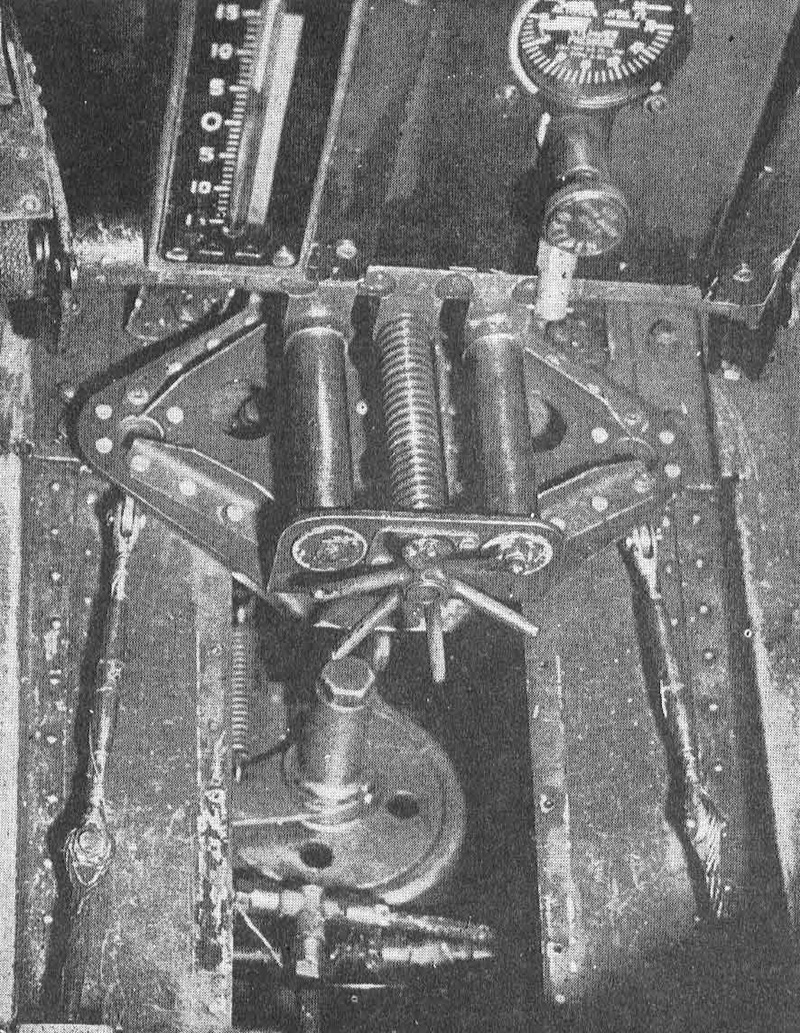
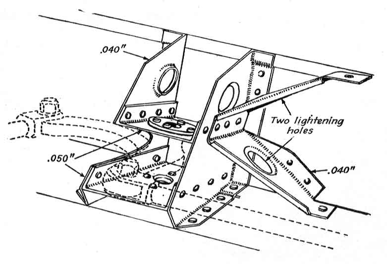
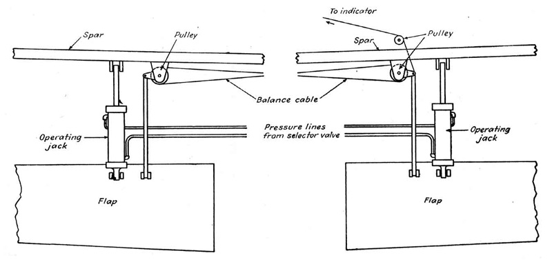
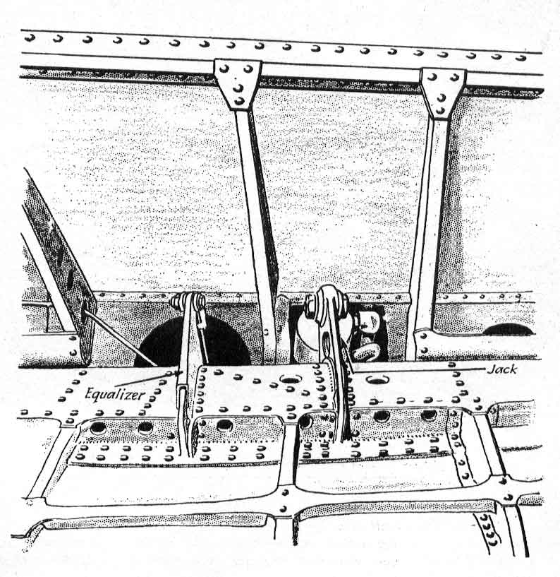
Flaps are hydraulically operated all-metal split type, with the skin flush-riveted to nine stamped, flanged ribs, a spanwise hat section stringer and a single spar which is combined with the leading edge by a heavy skin to form a torsion box. Flaps are attached to the false spar by piano hinges. The ribs are .020 gage; skin is .062 on the bottom of the torsion box, .017 aft; and spar is .050 dural. This spar is not continuous, being broken to receive brackets holding the operating balance gear and the hydraulic cylinder, which is attached to the flap, with the piston attached to the false spar. A plywood strip is screwed onto the trailing edge for added stiffness with little extra weight. Maximum deflection is 60 deg., but test flights have shown that 40 deg. gives the best glide angle. To insure balanced action, two 1/4-in. cables are attached to high tension leads installed aft of the false spar and connected through bell cranks and push-pull rods. Operation of the flaps is indicated in the cockpit by a graduated slide operated by a thin flexible cable attached to the balancing bell crank on the starboard flap.
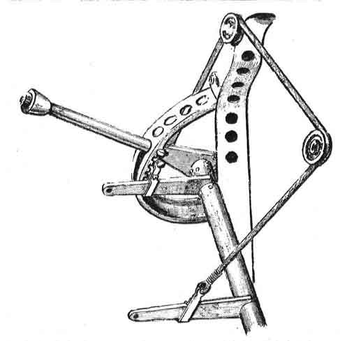
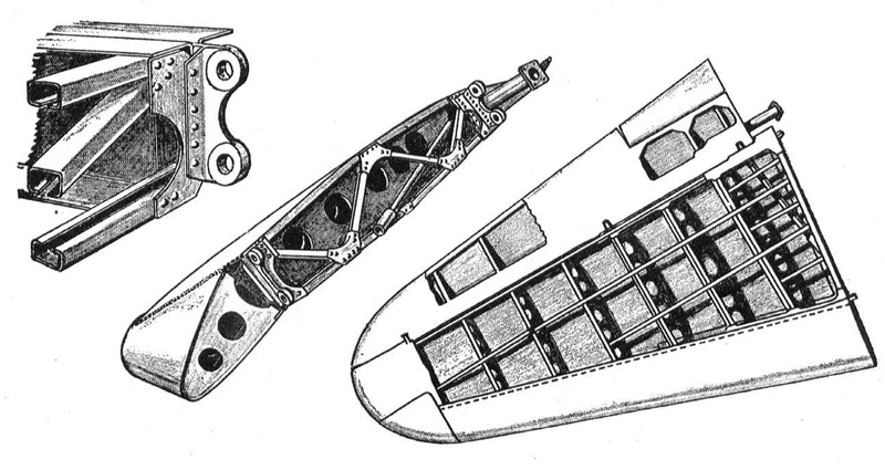
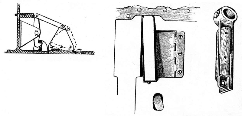
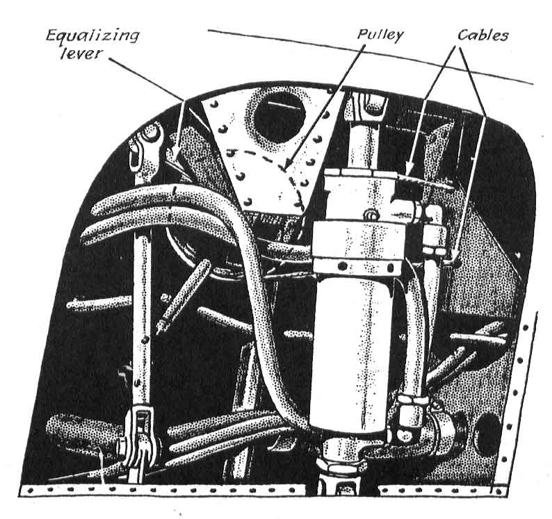
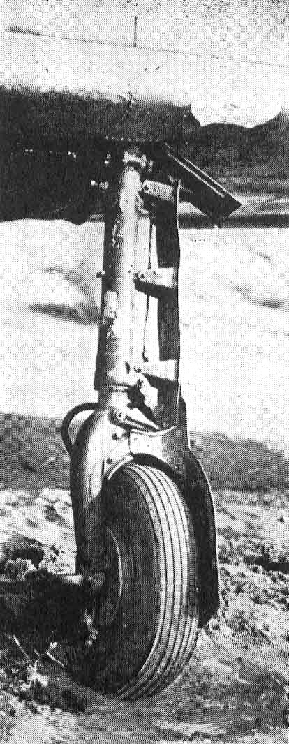
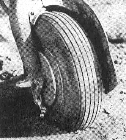
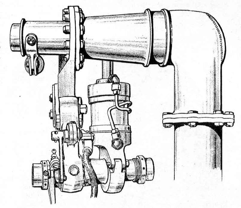
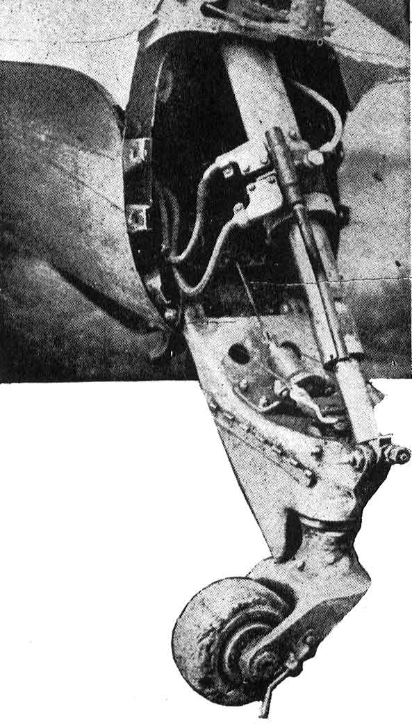
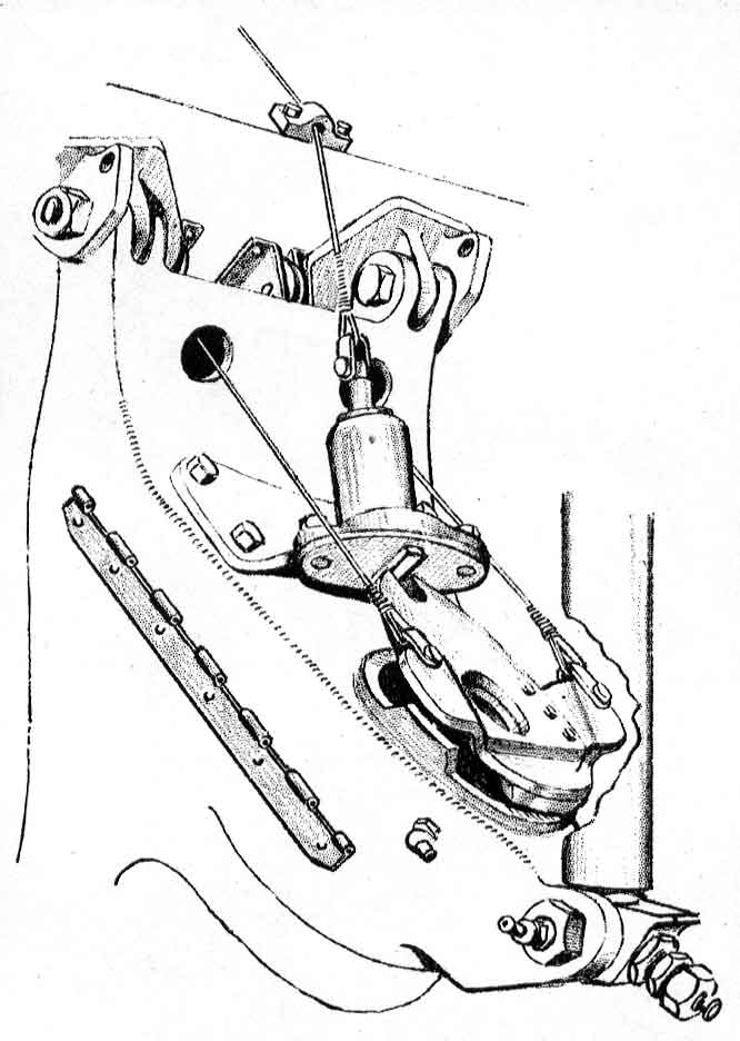
Landing GearOutstanding feature of the main retractable landing gear is the mounting of the retracting jack to the shaft through eccentric bearings which, when the strut has completed the downward arc, brings the linkage through to a straight line position to form a positive mechanical lock. To retract the gear, a cable attached to a cam controlling the lock arms is operated from an extruded arm on the landing gear selector valve handle. As this is moved to "up" position, the cam forces the lock arms from their position against the link plates as fluid pressure is passed to the rear of the 3 x 5-in. cylinder. As the piston connection to the leg is in straight position, and the cylinder mounting or secondary shaft is off center at the .eccentric, the pressure forces the cylinder backwards, rotating the shaft to bring the linkage from the straight position. At the top of the arc a ring on the wheel fork catches a latch in the wheel well to lock it up. when a micro switch turns on a red light on the electric switch box at the pilot's left. The pilot must then return the selector valve to neutral position, otherwise the hydraulic pump will continue exerting pressure and the system will burn out. A warning horn blows if the pilot fails to neutralize the lever after the wheels are up and locked, but it doesn't blow if he forgets to lower wheels when coming in for a landing. A green light on the switchbox indicates wheels are down and locked; a yellow light indicates they're neither up nor down. There is also a small bayonet indicator which projects above the left wing to give the landing gear position, similar to the Focke-Wulf 190. Also on the wheel fork is a small trip and roller which closes and locks fairing attached to the fuselage belly so that retracted wheels are completely enclosed. When the craft is on the ground and its weight causes the oleo to shorten, a flexible cable running from the right wheel up into the cockpit forces a small pin out behind the selector valve handle thus preventing its being moved into "up" position to retract the gear. The landing gear has a spread of 11 ft. 6 in., and in extended position the legs toe in 2 deg. and the wheels toe out 3 deg. Brackets and fairing attached to oleo and wheels are of .040 gage. Typical of the light weight of the craft are the wheel and 23 x 6.9 tire, together weighing but 28 lb. Brakes are hydraulically operated self energizing type with two shoes, 9 1/2 in. long, 1 3/4 in. wide and 3/16 in. thick operating on a steel drum riveted to the wheel. The brakes are usually operated by cables running from the rudder pedals, but some of the craft have the cylinders located in the fuselage. No parking brakes are provided, apparently just to save weight. Landing gear legs are conventional steel forging construction, 3 1/2 in. in diameter, with 3-in. diameter oleos having a 3 1/2-in. stroke and operating under approximately 230 psi., mounted atop wheel forks of welded steel stampings. The retraction unit is housed ahead of the front spar in a 21 1/2 x 10 1/2-in. section built up of 1/8-in. dural. Landing loads are carried directly into a short auxiliary spanwise spar and into the front spar by two heavy nose ribs and toward the rear spar by two interspar compression struts. The built-up section puts both landing gear leg and wheels forward of the front spar without bending it.
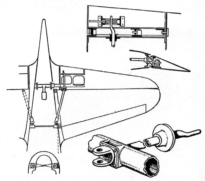
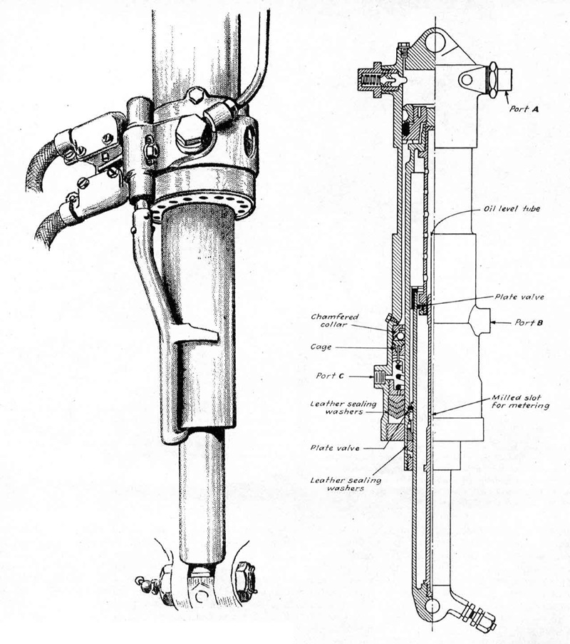
Tail WheelThe tail wheel unit is a combination retracting ram and air-oil shock unit, retraction being operated by the landing gear selector valve. The light alloy cylinder of the retracting unit houses a hollow ram, at the top of which is a piston head. Just above the compression glands on the piston head is a semi-circular groove, and when the ram is fully extended, two round headed spring-loaded plungers engage in a groove and keep the ram from moving outwards until pressure is exerted at the top port, indicated by (A) in the accompanying drawing. Right below the piston is another groove accommodating 14 steel balls when the ram is fully extended. The balls are retained in a cage towards the front of, but inside a packing gland, and are pressed up against a chamfered collar by a spiral spring against a glanded collar. The fluid pressure. supplied to the top port (A), is also connected with another port, shown at (C) in the sketch. This pressure, in conjunction with the spiral spring, pushes the balls against the chamfered collar, forcing them into a groove below the piston when ram is fully extended.
To retract the unit, pressure on the two ports (A) and (C) is released and applied to another lower port (B). Owing to the chamfered edge of the groove in the ram and release of the pressure, the balls are forced back into the cage and the ram travels back into the cylinder until locked by two plungers. All glands in this portion are leather, there being three main sealers of V-section forced between convex and concave collar-by the gland nut. The shock unit is in the retractor ram. From the piston end there is screwed a steel tube of 1/2-in. ID. and 3/4-in. OD. A series of 3/16-in. holes are drilled through the sides, starting 1/2-in. from the end. About 3/4-in. from the end is a shoulder against which is fitted a bronze collar with six 1/16-in. holes bored through the face and against which a plate valve works to control the six holes. The bronze collar becomes a piston fitting snugly into the bore end of the other portion of the unit which, in turn, slides into the internal bore of the retractor ram and becomes the shock absorbing, ram at the end of which is a pivot pin hole for attaching to fuselage former V. Up the center of the shock ram is fitted a hollow extension approximately 1/2-in. in diameter with a 5/32-in. steel tube right through the center and projecting 2-in. above the 1/2-in. brass column. Fluid is fed into the unit from a charging valve through the 5/32-in. tube which acts as a level tube. The brass column has a 1/16-in., 4-in. long groove tapering in depth from 3/32-in. at the top to 0 at the bottom. This tube is a snug fit with the tube fitted to the top portion of the shock unit, and in action is a metering pin. On impact, the shock ram moves inward, compressing the fluid and closing the valve on the piston forcing the fluid through the metering pin groove. which in turn allows it to flow through the large holes in the side of the tube in which the pin travels, to the main cylinder space. On recovering,: the compressed air forces the ram outwards, opening the plate valve and taking the fluid' back into the original chamber. The charging valve is situated in an offset on the end of the shock ram near the pivot hole. Gland pickings in the shock unit are fabric and a little leather. The lower end of this retracting-shock unit is attached to the aft end of the magnesium casting drag yoke, which is pivoted at its fore end to fuselage former V. Through this yoke a 3 1/2-in. long vertical pin turning in ball bearings attaches the aluminum wheel fork casting. The tail wheel itself is 5 3/4-in. in diameter and 3-in. wide, and has a 3/4-in. thick solid rubber tire. The bottom of the drag yoke is reinforced and shaped like a skid to reduce damage to the fuselage bottom in case the wheel stays retracted during a landing. The tail wheel is steerable by cables from the rudder through an arc of about 60 deg but full swiveling can be accomplished by giving the tail a sharp sidewise jerk which overrides the dogs tending to keep it within the normal arc. It can also be locked for takeoff or landing by a cockpit-operated spring-loaded pin which drops into the front end of the steering horn.
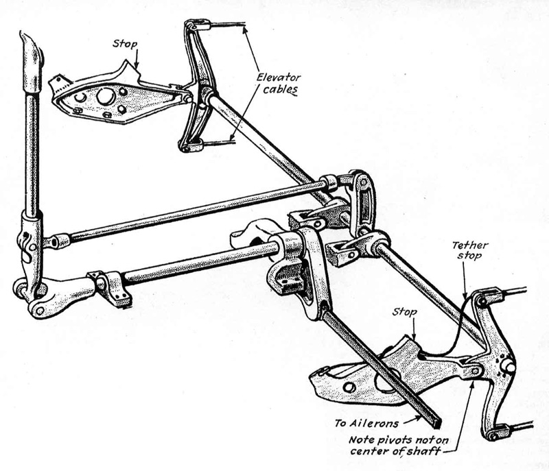
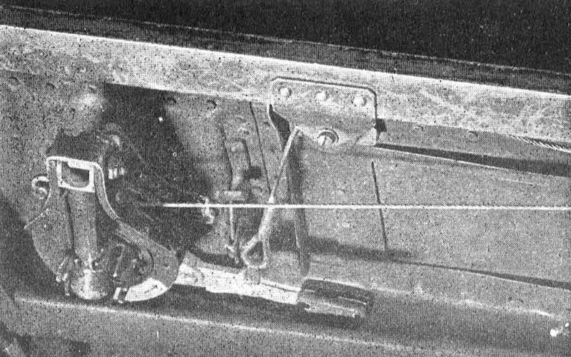
ControlsControls present quite a mixture of the old and fairly modern, for bearings, as an example, run all the way from the plain to rollers, and the only way to repair some of the units is to completely replace them. And in some cases this is no 5-min. job, since most units are riveted in place.. The control stick is made up of every light stampings and tubing, and apparently weight-saving was the dominant factor in its design. Aileron control consists of yoke at the base of the stick with a tube held by two plain bearing brackets running aft under the pilot's seat to a bell crank set just aft of the rear face of the rear spar. Push-pull rods of 1 1/4-in. diameter run from there to bell cranks set in built-up brackets at the center aileron hinges. Idlers to prevent buckling keep maximum length of the rods to 50-in. Elevator controls embrace a push-pull rod with rotating thrust bearing extending from the stick back under the pilot's seat to a self-aligning ball bearing bell crank held by brackets attached to the rear spar, with a torque tube extending out to bell cranks held by brackets riveted to the rear spar at the cockpit sides. These brackets have a built-in stop block to prevent pushing the stick too far forward and a cable stop limiting its backward motion.
Pivots of the bell cranks are set about 1 in. ahead of the spanwise tube, so that the cranks move up and down as the stick is moved. Quarter-in. cables extend from these cranks back through four different types of fairleads to the elevator horn. Obsolete is the best word for the rudder control design. Cables are attached to a diamond-shaped plate with the usual lightening holes-reinforced-by riveted flanges, the whole unit being set in a bracket attached to the top wing skin which forms the cockpit floor. Atop the plate are riveted two tubes and a screw jack on the aft end of which is a six-spoke wheel to give pedals a 4-in. fore and aft adjustment. The rudder bar is simply a bent alloy tube welded to brackets fitting over the tubes, and pedals are riveted to lugs welded to the outer ends of the bar. The hydraulic system is used only for the landing gear and flaps and is, therefore, a fairly simple unit. Pressure is supplied by a small gear-type pump driven by a gear train from the engine, and is regulated by a spring-loaded regulator valve adjustable between 782 and 853 psi. Excess pressure is by-passed through the valve into the 5 1/4-pint reservoir located in the fuselage behind the pilot. No accumulator is provided, pressure depending entirely on the pump.
Fuel SystemAn emergency hand pump, located on the right side of the cockpit, is coupled in parallel with the engine pump. Pressure lines have gauze filters which can be removed and cleaned without loss of pressure. The selector valves are three-position type, using, co-axial bronze valves operating in a bronze insert in a dural housing. Pressure is always applied to the top of the cone to insure positive seating. Normal fuel capacity is 134 U. S. gal., with 20 in a 12 1/4-lb. fuselage tank set just aft of the firewall, and 57 gal. in each of two 24-lb. wing tanks set between spars and extending out 49 1/2-in. from the root. All the tanks are light welded aluminum, are not self-sealing or protected in .any way, and are not an integral part of the aircraft structure. Hookup is conventional parallel, with a 4-vane engine driven pump backed by an emergency hand pump, and no internal by-pass or regulator is provided. Small tank ventilators are set in the lower surface of each wing; apparently cooling is necessary to prevent vapor lock at high altitudes, since no booster pump is provided. One of the two hydrostatic gages is connected to a two-way valve so that either wing tank can be measured; the other is for the fuselage tank. There are also two selector valves-one for wing tanks and one for fuselage and drop tank-with the cocks set in the wing center section and operated by a series of knuckle joints. In the center of the front spar is a permanent fitting for an 87-gal. drop tank, a very clean little unit that leaves no projection outside the fuselage once the tank is dropped. 'Most drop tanks are light aluminum, but some of wood and even compressed paper have been used by the Japs. The oil system includes a 13-gal. tank supported by welded lugs which bolt to the front of the firewall. The oil radiator is in a scoop just below the engine cowling, and shutters are operated mechanically through cables from a small crank on the right side of the cockpit. Electric SystemLight weight is again apparent in the two-wire electric system, current for which is supplied by an engine-driven generator and a 12 v., 20 amp. battery. Switches are simple but rugged, light wiring is used throughout, and conduits are small. It is interesting to note here that in many places throughout the craft, conduits, wires and plumbing are not held in place by brackets, but simply by shellacked tape tied into lightening holes found practically any place. Although Hamp's armament has been fatal to too many good Americans it is, compared with our fighters, lightweight like the rest of the craft. It consists, fortunately, of but two 7.7-mm. machine guns and two 20-mm. cannon. The machine guns, of comparatively low muzzle velocity, are built just like British Vickers. They have a free-firing rate of 600 rounds per min., but since they are electrically synchronized to fire through the propeller, their actual rate is much lower. The 20-mm. cannon are also of fairly low muzzle velocity and set outside the propeller arc, fire 100 rounds per min. | ||||||||||||||||||||||||||||||||||||||||||||||||||||||||||||||||||||||||||||||||||||||||||||||||||||||||||||||||||||||||||||||||||||||||||||||||||||||||||||||||||||||||||||||||||||||||||||||||||||||||||||||||||||||||||||||||||||||||||||||||||||||||||||||||||||
|
All material not specifically credited is Copyright © by Randy Wilson.
All rights reserved.
|